The first thing to build is a piston ballast. I’ll use the same syringe I did in Submarine 1.0, since it worked very well. It didn’t even leak 5 meters under water, so it should handle at least 0.5 bar of pressure.
The syringe
The syringe is a food syringe or marinade injector created by Eotia. It cost 4 euros in a Finnish hardware store, link: https://www.puuilo.fi/marinadiruisku-60-ml
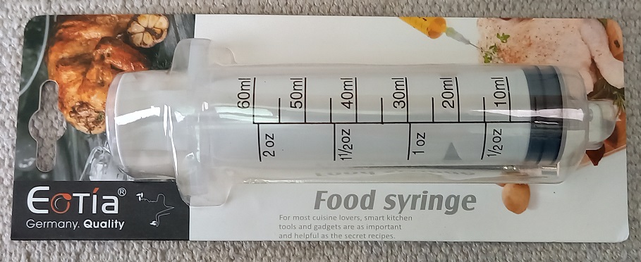
The capacity is 60 ml. That should be enough based on my experiences with the first submarine. The hull volume will be roughly 2000 ml, so the syringe will have about 3% control range. Of course you would like to have more capacity to provide safety in case the hull leaks or compresses. Also, fine-tuning the extra weights to neutral buoyancy would be easier. But larger syringe also takes more space inside the hull, so it is a compromise.
Actually, Submarine 1.0 used only 25 ml of the available 60 ml capacity. That was because it was driven by a Lego linear actuator, part id 61927c01, which has a short range. The linear actuator is also weak, as it couldn’t empty the syringe in 5 meters under water. Max pressure for control was about 0.3 bar.
This time I want to try a different build, to get more range.
Build
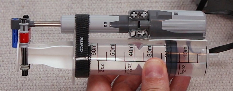
I put gear racks, Lego part id 3743, alongside the syringe rod. A little grey part to the end to help hold the rack lines in place.

The biggest problem was to push gears hard enough against the racks so they won’t skip. I put two 8-tooth gears (10928) to push the rod from both sides, therefore supporting each other. They would also help to hold the gear racks in place. Luckily all dimensions were good so all parts fit very tightly.
Then I used one of the syringe handles to hold the gears in place lengthwise, to the direction of the rod. This required a lot of trial-and-error until I found a Lego part combination that wouldn’t break.

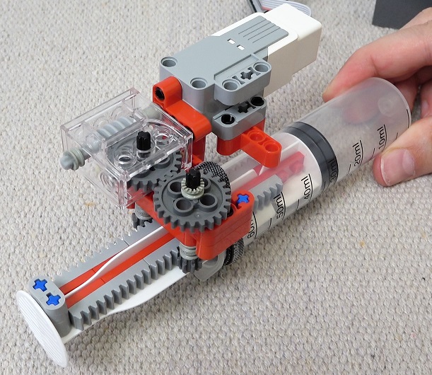
Lastly, I needed to gear down to provide enough torque. Lego gearbox, part id 6588, has a 24:1 gear reduction. It needs a worm gear (4716) and a 24-tooth gear (3648) to work. Besides increasing torque 24-fold, minus friction, it is very compact, perfect for a submarine.

The Lego motor I selected was EV3 Medium motor, because it has a tachometer inside that I can use to keep track of the syringe position.

I tested the construct for max pressure using a Lego manometer (64065). At first Lego parts slipped out of the handle when pressure increased to 0.3 bar. I put a Deltaco Velcro Strap around to pull the syringe and Lego parts together. That increased the max pressure to 0.5 bar. Beyond that I didn’t try, as parts started to bend dangerously, as you see from the image below. I did multiple tests to verify that it should work under 0.5 bar, which equals 5 meters of depth. But to be safe, I decided to limit the submarine depth to 4 meters.

The syringe speed is 2.7 ml/sec. Not very fast. Moving from min to max position (3 to 45 ml) takes 16 seconds. This will make the submarine react slowly to depth control changes. But as it turns out, it is enough for PID control.
So, the construct provides enough force. Actually too much. I had to be careful not to let the syringe run to the end, because it would probably break teeth from the gears. That was a problem. I briefly tried to replace 24-tooth gears with Lego clutches (60c01) that are designed to limit torque, but then the max pressure dropped to 0.17 bar. No good.
How to save the gears from destroying themselves? I resorted to tachometer data. I’ll read tachometer pulses and put limits to code on how the syringe is controlled. That was a source of annoyance further down the road, as Raspberry would not always catch tachometer pulses. Therefore I had to routinely check the syringe position data and tune it.
Wirings
Lego EV3 Medium motor is connected to Raspberry using a Lego EV3 cable. I cut one EV3 cable and crimped female DuPond connectors to the end.

The cable has 6 wires. M1 and M2 are for driving the motor. TACHO A and TACHO B for reading the tachometer pulses. GND and VCC are used to power the tachometers.
You should supply VCC with 5V according to the specs, but that is not an option, as the tacho pulses would have too high voltage for Raspberry to read them directly. Therefore I’ll supply VCC with 3.3V. I’ve used that setup previously with my Reaction Wheel Inverted Pendulum, and it works. I also have checked that the current draw from VCC is 6.5 mA, which is small enough for Raspberry.
Code
Then I wrote a Python code to read the tachometers. There are two tachometer signals and you know the direction of rotation based on which signal goes to 1 first. The code looks more complex than it should be, but that is because it provides the most reliability. E.g. you can’t read tachoA.value in the signal handler, because by the time that code is executed, the value has already changed. I tested multiple implementations with my Inverted Pendulum. As a side note, you could improve reliability by doing sleeps in the main control loop in small increments. I guess the rising/falling edge detection needs the CPU to be idle or something.
tachoPower = DigitalOutputDevice(20)
tachoA = DigitalInputDevice(16)
tachoB = DigitalInputDevice(19)

tachoAValue = tachoA.value
tachoBValue = tachoB.value
def tachoA_rising():
    global tachoCount
    global tachoAValue
    global tachoBValue
    tachoAValue = 1
    if tachoBValue == 0:
        #A in rising edge and B in low value
        #  => direction is clockwise (shaft end perspective)
        tachoCount += 1
    else:
        tachoCount -= 1
def tachoA_falling():
    global tachoAValue
    tachoAValue = 0
def tachoB_rising():
    global tachoCount
    global tachoAValue
    global tachoBValue
    tachoBValue = 1
    if tachoAValue == 0:
        tachoCount -= 1
    else:
        tachoCount += 1
def tachoB_falling():
    global tachoBValue
    tachoBValue = 0

tachoA.when_activated   = tachoA_rising
tachoA.when_deactivated = tachoA_falling
tachoB.when_activated   = tachoB_rising
tachoB.when_deactivated = tachoB_falling

tachoPower.value = 1
Syringe position is calculated from the tacho count. I included hysteresis calculation into the code to compensate for gear backlash and such things.
Syringe range was set to be between 3 ml and 45 ml. Minimum was 3 to provide some safety from hitting the end, and max was 45 because the hull doesn’t have more room.
SYRINGE_POS_MIN     = 3     #syringe ballast min pos [ml]
SYRINGE_POS_MAX     = 45    #syringe ballast max pos [ml]
SYRINGE_TACHO_COUNT = 19000 #tacho count from syringe min to max pos
SYRINGE_HYSTERESIS  = 360   #motor+gearbox+syringe backlash/hysteresis [tacho counts]

#calculate syringe position
if tachoCount > trueTachoCount:
    trueTachoCount = tachoCount
elif tachoCount < trueTachoCount - SYRINGE_HYSTERESIS:
    trueTachoCount = tachoCount + SYRINGE_HYSTERESIS
syringePos = SYRINGE_POS_MIN + SYRINGE_POS_MAX * \
             trueTachoCount / SYRINGE_TACHO_COUNT  #[ml]
I need to store the syringe position in flash, so that it is not lost during shutdown.
import configparser

#read config file
configFile = open("submarine_4.ini", "r+")
config = configparser.ConfigParser()
config.read_file(configFile)
tachoCount = int(config['default']['tachoCount'])

storedTachoCount = tachoCount
def writeConfigFile():
    global configFile
    global config
    global tachoCount
    global storedTachoCount
    if tachoCount != storedTachoCount:
        storedTachoCount = tachoCount
        config['default'] = {}
        config['default']['tachoCount'] = str(tachoCount)
        configFile.seek(0)
        config.write(configFile)
        configFile.truncate()
Here are the syringe motor output pins.
#prepare motor drivers
motorDive = DigitalOutputDevice(13)
motorSurface = DigitalOutputDevice(12)
Here is code for driving the motor. syringeMotorCtrl is the PID output. If syringe position is out of limits, the motor is not driven.
#syringe range limitations
if syringePos <= SYRINGE_POS_MIN and syringeMotorCtrl < 0:
    syringeMotorCtrl = 0
if syringePos >= SYRINGE_POS_MAX and syringeMotorCtrl > 0:
    syringeMotorCtrl = 0

#drive syringe motor
motorDive.value = (syringeMotorCtrl > 0)
motorSurface.value = (syringeMotorCtrl < 0)
I also added a deadband limit to reduce motor wear, as the PID output is noisy. More of that when testing PID.
Tests
Here is the syringe position data from a typical swimming pool test run. The submarine dives to the bottom, drives around, and comes back up. PID control is in use.

As you see, the active range for operation is about 25 ml. That is about half of the syringe size. Therefore the syringe is large enough for control.
In the 10+ hours of testing the submarine, the syringe worked physically well. I never noticed any leaks. Then again, it was tested only at a max depth of 1.5 meter.
Two times the range limitation failed and the syringe ran against the end. The first time the tacho count was wrong after a long test run. The second time I had made a change to the code that crashed it, leaving the syringe motor on. No teeth was broken in either case, but the gears slipped out of the gear rack and I had to install them again. The fact that Raspberry failed to catch tacho pulses and the actual syringe position would be lost in time, is the biggest complaint I can see with the syringe. It was annoying to need to check the position data and tune it between test runs.

Just posting a comment here so you know someone actually reads these lololol. I love how in depth you go with these posts, and I hope you can do that someday with your YT videos as well!
LikeLiked by 1 person
Thanks mate!
LikeLiked by 1 person
Your submarine is really amazing!
Did you take a look at interrupts? They are commonly used to read fast pulses like the tachometer. Hope that will help you!
LikeLike
I think those when_activated events come from hardware interrupts. At least I hope. But yeah, that would be one way to improve it, to find better real time interrupt handlers.
LikeLike
Also, looking at the data of the test, those spikes are probably the “derivative kick”, as described here: http://brettbeauregard.com/blog/2011/04/improving-the-beginner%E2%80%99s-pid-derivative-kick/
LikeLike
No, the “derivative kick” was already fixed in those tests. The fix I used was to just reset the derivative when set point changes. Code is in the 9/10 post. That article you linked actually presents a better way to do it, more accurate and only slightly more complex.
LikeLike
Is there a particular reason to use a Pi instead of a plain MCU like the Pico? These should give you much more control over readings and tighter timings if needed.
LikeLike
I first considered Pico but I needed more flash memory to store log files. That’s why I selected Raspberry Pi Zero 2 W.
LikeLike
Fantastic work!
re: rp2040: some of the rp2040’s have extensive flash storage, and one could log to external sd cards.
one benefit of the 2040s is the state machine code (PIO) which could assist in catching the tach pulses. perhaps look at Circuit Python and pioasm https://docs.circuitpython.org/projects/pioasm/en/latest/index.html
LikeLike
Great build! Maybe I missed this, but I assume the syringe is ported to the exterior?
LikeLike
Yep. A silicone tube through the front lid. Explained in 3/10 post.
LikeLike
This is awsome! For a lego lover, mech eng and nautical passionate like me, you’re like Walt Disney making dreams come true!
Congrats and thank you for sharing
LikeLike
Great project!
LikeLike
Hi, excellent work ! What about testing syringe piston end positions with some optical sensors (black piston rubber in end position will block light from source to sensor) ?
LikeLike
Yeah, why not. The optical switch would stop motor and also reset tacho count to reduce error accumulation. Hall sensor + magnet could work also as a switch. Or use plain electronic switch.
LikeLike
Yeah, you could use pre-made endstops, common in 3D printing.
LikeLike
your submarine is really awesome!
I plan to use it as my graduation project!
LikeLike
Hi, great article! Two questions if you don’t mind! (1) Just curious, where did you get the specs for the EV3 motor? This article cites the voltage at 5V but according to several folks over n the r/lego subreddit, they claim its rated at 9V! Do you know where I can find a spec sheet?
And similarly, (2) where did you find the pinouts on the EV3 cable port? How did you know which pin was, say, VCC and which one was TACHA, etc.? Thanks for any insight here!
LikeLike
Hi. Here are specs for the EV3 cable pinout, page 5. https://www.mikrocontroller.net/attachment/338591/hardware_developer_kit.pdf
Here is another image to help with the colors. http://www.bartneck.de/wp-content/uploads/2015/06/connection-diagram.jpg
I think you have a mix up with two things: driving the motor and powering the tachometer. The M1 and M2 pins (named PWM signals in the specs document) drive the motor. You can put 9V into those pins, like the subreddit folks said. VCC powers the tachometer. That should be supplied with 5 Volts (but works also with 3.3V as I have noticed).
LikeLike
Perfect, thank you for the links and the clarification. One last followup question if its OK: I searched high and low for the first link (the EV3 spec sheet/PDF) and couldn’t find it. How and did *you* find it? Is that website a collection of all “old” lego spec sheets? Does lego.com make these available from anywhere off their site?
I guess my thinking is: if you can show me how you knew where to look for this, I can avoid having similar problems in the future. Thanks again so much for any-and-all help!
LikeLike
I just use Google image search. If you search for “ev3 pinout”, one of the top results is an image from that particular pdf document, page 5, figure 2, where the pins are specified.
LikeLike
Hi, thank you for this in-depth blog, it’s such a cool project! I’ve been trying to replicate the syringe motor and i’ve hit a wall, i just can’t get the motor to turn. Any troubleshooting tips would be appreciated!
I’ve connected:
– VCC to GPIO20
– GND to Physical Pin 34
– TachoA to GPIO16
– TachoB to GPIO19
– M1 to B2 OUT
– M2 to B1 OUT
– I’ve measured VCC (3.3v).
– I’ve measured B1 and B2 OUT (8.2V and -8.2V).
– I’ve verified the EV3 pin layout (my wire has opposite color order, blue=M1, white=TachoB).
– I’ve checked the health of the gpio pins with gpiotest.
– I’ve verified the tacho gpio pins are set to input with gpio readall.
– I’ve tested multiple motors EV3 medium and large.
– I’ve verified the motors work when connected directly to the battery with a third-party power-functions to EV3 cable.
I’m not sure what to try next.
LikeLike
Hi Tom. Do you know that only M1 and M2 pins are needed to turn the motor? You don’t even have to connect the other pins. That will simplify your problem solving.
I would first verify that the motor turns when you connect M1 and M2 for example to the + and – of a 9V battery. Then I’d verify with a multimeter, what you already did, that the B1 and B2 OUT voltage difference is around 8V when you run your program. Then I’d check that the B1 and B2 OUT voltage stays in 8V when the motor is connected, to verify that your power supply can handle the load. If all those checks pass, the only thing left is a bad wire connection between B1 and B2 OUT and the motor.
LikeLike
Thank you for this. It turns out the M1 wire had a bad connection in the RJ45 connector. It was intermittent, so when I connected M1 and M2 straight to the battery it worked the first time, then stopped working when I connected it to the motor driver, which made debugging fun. Solved with a new cable.
LikeLike
Hi,
Great project! I have just started with my son to replicate it and have a quick question. In the picture with the syringe ballast the ev3 medium motor seems to be connected to the battery with red (gnd) and black (m2) pins, or is it m1 and m2?
Thanks a lot
LikeLike
Hi. The image with the battery box? It is m1 and m2. Those black and red wires in the image are just short jump wires that behind the motor connect to m1 and m2. Confusing, I know. 🙂
LikeLike
Thank you
LikeLike
This is all so amazing. Just so you know I am using this series as a means to teach my friend’s children about science and software. They are fascinated and I couldn’t imagine a better way to teach kids. Thank you so much for this entire series.
LikeLike
Hello,
Amazing build !
I have one question: I can’t get my head around how you attach the lego ensemble to the syringe handle (“Then I used one of the syringe handles to hold the gears in place lengthwise, to the direction of the rod. This required a lot of trial-and-error until I found a Lego part combination that wouldn’t break”)=> how to you fit the width of the handle between the lego parts (which I suppose from the picture, should touch each other) ; I think I’m missing something, if you can shed some light on this (or share additional pictures) it’d be super helpful 🙂
Thanks a lot!
LikeLike
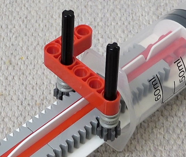
No problem. Here is one additional image. Two 2L liftarms, connected with a pin, are placed in the middle to grab the handle.

There is actually a small gap between parallel liftarms. Very small, 0.5 mm or something. Like shown in this image.

The syringe handle is a little bit thicker than that. But it fits there if you push with a small force. Lego plastic bends a little.
LikeLike
Thank you very much, got you !
LikeLike
Hi, I’m recreating this project for one of my college projects. I have everything wired and ready to go, but my Raspberry Pi 4 shows an error when trying to unzip your files. It says “error while accessing the archive”. Any ideas?
LikeLike
When running the submarine.py code, I get an error in line 76.
bus = smbus.SMBus(1)
File Not Found
LikeLike
For the SMBus error, check that you have I2C enabled in the Raspberry Pi configurations. How to: https://youtu.be/WObG2LoSEwQ?t=41
LikeLike
Do you know why I would get an error while unzipping the files that says “error while accessing the archive”?
LikeLike
What files are you trying to unzip? I haven’t shared any zip archives in this blog.
LikeLike
I was trying to unzip your files for all the code for the submarine, but I figured it out. I have it all wired up, I just keep running into errors trying to run the code.
I appreciate the responses. I do have other questions if you don’t mind:
I seem to be running into errors in the code with relation to the radio control and the laser distance sensor
LikeLike
I don’t remember doing anything special for the laser distance sensor. Just connect it to the UART pins (GPIO 14 & 15) and provide 5V power. Maybe try swapping the UART wires if they are in wrong order. Maybe also check that enable_uart=1 is written on /boot/config.txt
Have you looked at the close-up images and the wiring schematic here?
This is the schematic, zoom to see how the radio wires are connected:

LikeLiked by 1 person
Yep, me and my professor have done all of those options. Even with enable_uart=1, I am getting an error in the code.
I am using a Raspberry Pi 4 Model B, and the pinout is the exact same as you have. Now, I am supplying power using a micro-usb. Could this be causing some issues with serial0 or serial1?
LikeLike
What kind of error are you getting?
I didn’t experience any problems supplying power with a micro-usb to the Zero 2 W board.
LikeLike
Ok, we figured out the issue. Kind of embarrassing to admit, but we spent 3 hours today troubleshooting to find out we were not saving enable_uart=1 to the config.txt correctly!!
Now, your code runs with no issue. Our new problem is nothing is driving now that we are pushing buttons on the controller. I wish I could attach photos, but we have everything wired up and ready to rock, but no response from motors.
LikeLike
Great.
With the motors not responding to buttons, that should be basic problem solving. Divide-and-conquer. I’d first put print commands to the button handlers to see if the signals are received. If not, use a multimeter to check that the voltage on the radio board output wires changes as it should. And so on…
LikeLike
Thank you, I appreciate the help and the responses! I’m sure you’ll hear from me again.
I’ll have to send you photos when we get it all done!
LikeLike
That would be great. I’ve love to see photos. 🙂
LikeLike