Submarine needs a low-frequency radio controller that is able to penetrate water. At least 27 MHz, 40 MHz and 75 MHz bands should work.
Those are hard to find. Nearly all available radio controllers use 2.4 GHz. I’ve resorted to buying cheap toy submarines that use proper radio frequencies, and cannibalize them for the receiver board and use their transmitter. It is a sub-optimal solution, but it has worked well enough in my three previous submarines.
Once gain, I continued the same path, using the same no-name Chinese toy manufacturer as before.
A toy submarine
I bought a mini u-boat toy submarine of a chinese brand Mliu. It cost 33 euros in Amazon store TAIPPAN, link:
https://www.amazon.de/-/en/Control-Military-Electric-Rechargeable-Swimming/dp/B08T66M8P7/

The main criteria in buying this particular toy, besides the fact it uses 27 MHz radio frequency, was the nice looking transmitter this has. Very toyish, but it still appeals to my eye.
The transmitter has 6 buttons for control: left, right, forward, backward, dive, surface.
After I tested that the toy submarine works, I disassembled it. I cut all wires leading to motors and took out the single board it contains.

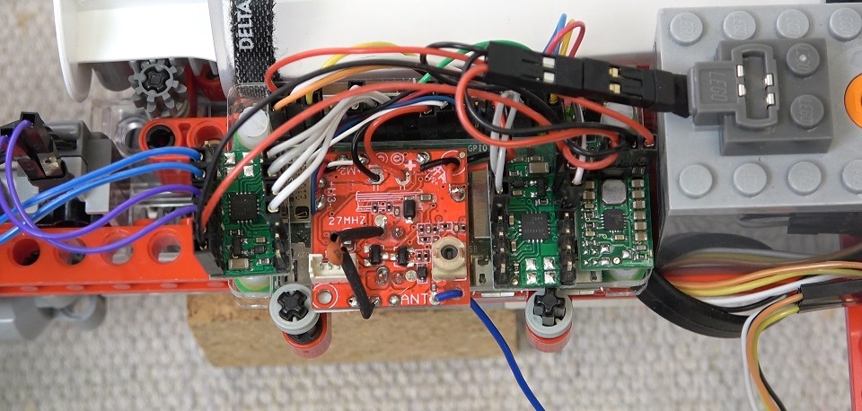
Here is the board that came out.

Here is a closeup of the board from both sides, after I removed the big green cylinder that was a LiPo battery.

External power supply
In previous submarines I’ve supplied the radio board with a LiPo battery. Now I wanted to remove that and use power from the Lego battery box. It would make recharging the submarine easier, as there would be only one battery on-board.
But does the radio board work with voltage other than 3.7V it it designed for?
I tested it using an adjustable power supply, and found the minimum voltage that made the board function to be 2.3V. That means I can use the Raspberry Pi 3.3V output to power up the radio board. Great!
I also verified that the control range was not affected. It was around 7 meters regardless of supply voltage.
Connection to Raspberry
First I checked if I need pull up/down resistors to protect the Raspberry. Raspberry GPIO pins can take 0-3.3V. I measured voltage from the radio board motor wires that I’m using to read button presses. The voltage was either 0V or 3.3V. Great, I can connect them directly to Raspberry.
Then I connected the wires to Raspberry GPIO pins. 6 wires for buttons, one ground wire and one power wire.

Code
I first created Button instances for all the GPIO inputs and one output for powering the radio.
#prepare radio control
radioPower = DigitalOutputDevice(25)
buttonForward = Button(24, hold_time=1.0)
buttonBackward = Button(23, hold_time=1.0)
buttonLeft = Button(9)
buttonRight = Button(10)
buttonDive = Button(11, bounce_time=None, hold_time=1.0, hold_repeat=True)
buttonSurface = Button(8, bounce_time=None, hold_time=1.0, hold_repeat=True)

tachoPower.value = 1
Then for left and right buttons I added handlers that write values to the motor output. Here is a snippet of the relevant parts.
motorLeft = DigitalOutputDevice(17)

def buttonLeft_pressed():
    motorLeft.value = 1
def buttonLeft_released():
    motorLeft.value = 0

buttonLeft.when_pressed      = buttonLeft_pressed
buttonLeft.when_released     = buttonLeft_released
For forward and backward buttons I added a little crawl period for the first second, in which PWM duty cycle is only 60%. It helps maneuvering in tight places.
motorForward = PWMOutputDevice(22)
motorForward.frequency = 1000

def buttonForward_pressed():
    motorForward.value = 0.6
def buttonForward_held():
    motorForward.value = 1
def buttonForward_released():
    motorForward.value = 0

buttonForward.when_pressed   = buttonForward_pressed
buttonForward.when_held      = buttonForward_held
buttonForward.when_released  = buttonForward_released
Surface and dive buttons don’t control motors directly, instead they change target depth or target distance for the PID controller.
def changeTargetDepth(value):
    global controlMode
    global targetDepth
    global targetDistance
    if controlMode == MODE_PID:
        targetDepth += value
        if targetDepth < 0:
            targetDepth = 0
        if targetDepth > MAX_DEPTH:
            targetDepth = MAX_DEPTH
    elif controlMode == MODE_PID_LASER:
        targetDistance -= value
        if targetDistance < 0.1:
            targetDistance = 0.1
        if targetDistance > MAX_DISTANCE:
            targetDistance = MAX_DISTANCE

def buttonSurface_pressed():
    changeTargetDepth(-0.05)
def buttonSurface_held():
    changeTargetDepth(-0.5)

buttonSurface.when_pressed   = buttonSurface_pressed
buttonSurface.when_held      = buttonSurface_held
Change control mode
I need to change between modes. The PID can be controlled using a pressure sensor or a laser distance sensor, so I need to change between those two. Also, I need to be able to bypass PID control and drive syringe directly, e.g. to empty the syringe after dive.
But the radio transmitter has only 6 buttons which all have a function already. The only way I can think of is to use button sequences. Three button presses in a certain order in 1.5 seconds to change the mode.
#change depth control mode
#  triggered by button sequences
#    MODE_DIRECT    = Surface-Dive-Surface
#    MODE_PID       = Surface-Dive-Right
#    MODE_PID_LASER = Surface-Dive-Left
changeMode = False
if buttonSurface.value == 1:
    if modeButtonStep == 0:
        prevModeButtonTime = perf_counter_ns()
        modeButtonStep = 1
    if modeButtonStep == 2:
        modeButtonStep = 3
        controlMode = MODE_DIRECT
if buttonDive.value == 1:
    if modeButtonStep == 1:
        modeButtonStep = 2
if buttonRight.value == 1:
    if modeButtonStep == 2:
        modeButtonStep = 3
        controlMode = MODE_PID
if buttonLeft.value == 1:
    if modeButtonStep == 2:
        modeButtonStep = 3
        controlMode = MODE_PID_LASER
if modeButtonStep != 0 and (perf_counter_ns() - prevModeButtonTime) / 1e9 >= 1.5:
    modeButtonStep = 0
Problem with auto-surface
While testing the board, I kept having problems with the surface button. The surface motor wire would turn on apparently by itself and the surface button stopped working. What was going on?
It took me awhile to figure it out. The manual calls it “automatic lifting function”. When no buttons are pressed within 10 seconds, the submarine will automatically rise to the surface. This is a new feature in this brand of toy submarine, which is why I hadn’t noticed it in previous submarine projects.
I spent a lot of time trying to bypass it. First I reverse engineered the operation principle. The little toy submarine has a piston ballast, like I’m making here. 🙂 The ballast has limit switches to indicate when to stop driving the motor. The auto-surface feature is waiting for the ballast to reach the limit, and then it will stop driving the motor. I connected the switch wire to Raspberry and put code in to trigger it every 5 seconds, to make the board think it is at surface. It worked most of the time, but sometimes the surface button still stopped responding. What made it worse, if the auto-surface thing was turned on only for a moment, you would need to press dive button once to reset it. Otherwise the surface button was dead.
Eventually, I came up with a brutal idea. I just reset the whole board. Since I’m powering it through Raspberry GPIO pin, I can control when to power it.
I put a code to reset the board very quickly every 9 seconds. Or more precisely, after 9 seconds of not pressing any buttons, since I can detect all button presses in code. The power is cut off for one loop interval, 25 ms, which is long enough to reset it.
#radio controller fix
#  the radio board has an auto-surface safety feature
#  after 10 secs of silence it will make the surface button to not work
#  to fix it, we will quickly power off and on the radio every 9 secs
if (buttonDive.value == 1 or buttonForward.value == 1 or
   buttonBackward.value == 1 or buttonLeft.value == 1 or buttonRight.value == 1):
    prevRadioResetTime = perf_counter_ns()
secsSinceRadioReset = (perf_counter_ns() - prevRadioResetTime) / 1e9
if secsSinceRadioReset > 9:
    radioPower.value = 0
    prevRadioResetTime = perf_counter_ns()
else:
    radioPower.value = 1
That took care of it – the radio worked always after that.
Problems with range
When I got to test the radio inside the hull, with Raspberry and all other parts running, I noticed the range was only 3 meters. That was odd. I had tested it before disassembly, and the range should be 7 meters.
Maybe extending the antenna will help? In my earlier submarines I added a longer antenna and increased the range from 7 to 10 meters. I tried it, but this time it had no effect.
Maybe the Raspberry’s noisy supply voltage causes frequency interference? After all, the voltage from Lego rechargeable battery box, that is initially clean, coming from two LiPos, goes first to a 5V switching regulator, and then to Raspberry’s internal 3.3V regulator, before reaching the radio board. So it probably has a lot of noise.
I tried to supply the radio from a clean power supply, and that seemed to fix the problem at first. Range was increased to 7 meters. But when I added a separate LiPo for the radio board, the range was dropped back to 3 meters. I was getting mixed test results.
Okay, maybe the radio picks up electromagnetic interference from wires and other parts inside the hull? After all, it is located on top of the Raspberry, very close to all other electronic parts.
I tried a few different locations. If the receiver was 20 cm away from other parts, range was 7 meters, but dropped to 3 meters when close to other parts. Okay, I’ll locate the radio board as far as possible inside the hull, about 10 cm away.

That increased the range to 4 meters. Still quite bad.
Once again I tried different antennas. 20 cm long straight antenna didn’t improve the range but a big looping antenna along the hull cylinder increased range to 6 meters at first. But when I tested it again in swimming pool, it had no effect, range was only 3-4 meters, which is the same range I got with a short 3 cm antenna.
At this point, I was having a lot of mixed information and test results. This radio interference feels like black magic. Probably all the things I tried have some effect, I just can’t measure it in any reliable way.
I gave up trying to fix it. The radio control range is only 3-4 meters, just deal with it. It was enough to do the tests and videos I needed to do, including tests in a swimming pool and through a very small river. But it was annoying, sometimes having to press buttons multiple times to get through.


Thanks for documenting this including all your troubles… Also, good to keep something to optimize for later on 🙂
LikeLiked by 1 person
You can get transceivers like that if you’re willing to buy from AliExpress and wait a month: https://www.aliexpress.com/item/2251832762660109.html
LikeLike
Resting the board every 9 seconds, brutal but genius!
LikeLike
You can try to insert the control board in a small plastic container, a bag or an envelope and then wrap it in aluminum foil, letting out only the antenna. If you want to avoid short circuits, wrap the card again with a plastic bag. Extend the antenna as far as you can inside the submarine and stay away from the Raspberry module. You should also try wrapping the Raspberry itself in aluminum foil using the same method. using tinfoil limits disturbing emissions. For best performance, the tinfoil should be connected to the negative pole of the battery.
LikeLike
Hi
I just done the radio board wires work, but i confused about 6 wires how to connect radio board pin direction, can you figure out the pin direction? match the 6 wires to radio board.
LikeLike
append two pics.


front side,
backed side,
LikeLike
Looks nice 🙂
Reading from my old notes, the radio board wires are these:
+/- holes are 3.7V power
M1 red/black wires are dive/surface
M2 white/black wires are forward/backward
M3 red/blue wires are left/right
ANT blue wire is antenna (not connected to anything)
I don’t remember the polarity. You just need to test it. It is easy to switch the pins to the code afterwards.
LikeLike
Thanks for sharing this info on the internals. Looks like there is a little space left inside. Are there any markings visible on the ICs (receiver, microcontroller, H-bridge, …)? Do you have more photos of the drives you could post?
I found this a little cheaper on Banggood (18 EUR with shipping to Germany). Incredible bang for the buck I think. Buoyancy is a little hard to control and needs a bit of luck with the timing – half the rate would probably be better.
The aft thruster steering works quite well – turns on the spot.
I have to say I envy your awesome YT income 8-D
LikeLike
No markings visible on the radio board ICs. Just black components.
Here is one additional disassembly photo of the toy submarine. On the ballast motor is printed “M20S-1190-19”.
LikeLike
Are you sure that “big green cylinder” is a LiPo? To me, it seems like a capacitor. If not, then it is a Li-ion battery (according to its description in amazon).
LikeLike
I measured it provides 3.7 Volts, so definitely not a capacitor.
The markings say Lithium Ion and UL: MH48909. I found it on Alibaba.
https://www.alibaba.com/product-detail/HCC1020-Cylindrical-shape-rechargeable-3-7v_1600160215129.html
So, yeah, it is not a LiPo. It is a Li-ion battery.
LikeLike
Hi, what is the range between transmitter and receiver both underwater please?
I need to know if I could replace the wired remote of my underwater scooter jetpack by a wireless one… Thanks for your reply !
LikeLike
The range underwater is a few meters. In earlier projects I used radio control successfully for a submarine that is 5 meters underwater (Sub 1.0) and 6 meters underwater (Sub 3.0). Both used the same 27 MHz toy submarine board. A water barrier doesn’t seem to affect the range much (for 27 MHz).
LikeLike
Okay, many thanks for your help .
Do you think it can achieve 1,5 meters between 27 Mhz receiver and transmitter both underwater with only a coil ferrite antenna instead a long one? Besause i couldn’t extend a long antenna under water, only a short or a small coil ferrite antenna as it can found on key fob ?
LikeLike
That’s out of my expertise, but I think you might have problems with a short antenna. With the blue transmitter I sometimes forgot to extend the antenna and noticed connection problems. The range was probably halved. The retracted antenna is 10 cm and the extended is 40 cm long.
LikeLike