Time to add electronic parts and connect wires for the submarine.
Computer
The computer’s main task is to control depth. It takes sensor data and drives the syringe motor in a control loop. The control loop doesn’t have to be fast as the submarine moves very slowly.
I first considered using Raspberry Pi Pico, which is a tiny micro-controller unit with a 133 MHz processor. CPU speed would have been enough, but unfortunately it contains only 2MB of flash memory. That would be too little for the amount of log data I want to store.
So I chose the next one in Raspberry Pi lineup, Raspberry Pi Zero 2 W. It was very difficult to get, because of the worldwide chip shortage, but I luckily found one available. It cost 28 euros, link: https://raspberrypi.dk/en/product/raspberry-pi-zero-2-w/
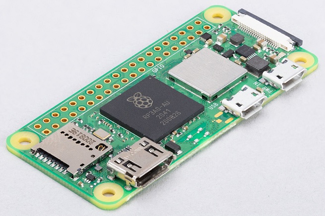
The board contains a 1GHz quad-core processor and 512MB of RAM, which is more than enough performance for me. I bought a 16GB microSD card to be used as a storage. That will provide enough space for any log files I am going to generate. The board is fairly small (65×30 mm) and will fit nicely into the submarine.
Wireless WLAN connection is also supported. It proved to be a lot more useful than I thought initially. It allowed me to change PID parameters and do fixes to the code without needing to open the lids and connect USB cable to the Raspberry. It made the development process a lot faster. An absolute necessity to have a WLAN.
Since I bought a headerless version, I needed to solder a pin header. I bought a colored pin header, which is much better than a black one. I had used the black header earlier, and it was annoying to count the pins to know where to connect wires.
For attaching and protection, I bought a clear case, which is two plates attached with screws onto the board. It cost 5 euros: https://www.partco.fi/en/raspberry-pi/sbc-housing/22446-rpi-zero-case.html

Then I needed to install the microSD card. Raspberry Pi provides a desktop imager program for it, which is easy to use. I installed Linux-based Raspberry Pi OS operating system onto the card.
A bit more difficult was setting up the communications. I have a laptop computer I want to connect to the Raspberry Pi, using both WLAN and USB cable, just in case the other one dies.
For the USB connection, I had to install Windows RNDIS driver to the laptop to enable Ethernet over USB. Then change a few lines of configurations to the microSD card. Link to the instructions.
For the WLAN connection, I turned the Raspberry into an access point, so that no external access point is needed. I will connect my laptop directly to the Raspberry AP using WLAN. It required a fair bit of configuring. Link to the instructions.
After the connection was up and running, I used VNC Viewer (RealVNC) remote desktop to access it.

I used Thonny Python IDE for running the code. It comes pre-installed with Raspberry Pi OS.

Location
I put the computer near the battery box, where there was most space left.

Two short Lego liftarms and axle pins were enough to hold it in place. No tape was needed.

Wirings
All wires were custom made, as there is little space inside the hull.
The wire thickness I selected is AWG28 or 0.09 mm2. Very thin and flexible, good for tight spaces. Difficult to know how much current it can precisely carry, as there are different numbers in different sources, but at least 1A should go safely. Enough for my needs.
I found this rainbow flat cable to be very good, as it provides many different colors. You just strip away the wire you need. It costs 1.5 euros per meter, link: https://www.partco.fi/en/cables-and-wires/flat-cables/7665-kaa-lat-10-vari.html

For connections I used pin header connectors (DuPond/Harwin connectors), since those are compatible with the Raspberry pin header. I bought a big connector kit that cost 20 euros, link: https://www.partco.fi/en/connectors/pin-header-connectors/pin-header-connectors/19454-liitinlaj-2.html

I also need a crimp tool to attach the connectors to wires. The one I used cost 22 euros, link: https://www.partco.fi/en/tools-and-handtools/crimp-tools/rest-of-crimp-tools/11353-ht213.html

Crimping is a particular skill. Watching how-to videos helped me to grasp it. Cutting the wire insulation to correct length was important for a clean result, as was to press the crimp hard on difference places for a secure connection.
Here is one finished wire.

Voltage regulators
Lego battery box output voltage is about 8V, but Raspberry takes in 5V. Need a step-down DC/DC converter.
I bought a Pololu 2123 S7V8F5 5V voltage regulator. It cost 20 euros. Link: https://www.partco.fi/en/power-supplies/dcdc-voltage-converters/20031-pololu-2123.html

The chip is very small (11×17 mm), which was my first criteria. Max continuous output current is 1A, which is enough for me as the Lego battery box cannot output more than that. Efficiency is about 90%. The input voltage range is 2.7-11.8V and output is 5V. Everything fits well.
It has four connections: GND, VIN, VOUT, and SHDN. The fourth one is a shutdown pin that we won’t need. So just three pins to connect.
Motor drivers
Next thing is to drive the Lego motors. Raspberry can provide only 3.3V and couldn’t handle the current anyways, so I need motor drivers. The drivers should be able to change speed and direction of rotation. H-bridges can do that when run with PWM signals.
In previous submarines I used L298N motor drivers, but later I found out from different sources that their efficiency is only 40-70%. There are better drivers available. TB6612FNG efficiency is over 90% and DRV8833 is 70-90%.
I had used TB6612FNG before in my Reaction Wheel Inverted Pendulum. Although better efficiency, it requires two connections (VCC and STBY) more than DRV8833. So, I chose DRV8833 for simplicity.
I bought two Pololu 2130 DRV8833 dual motor driver boards. One board can drive two motors. They cost 5 euros a piece. Link: https://www.generationrobots.com/en/401023-drv8833-dual-motor-driver-pololu.html

This chip is also very small (13×20 mm), great for a small submarine. Voltage range is 2.7-10.8V, good for a Lego battery box that outputs 8V. Max continuous output current per motor is 1.2A, well above my needs.
This one has many connections. GND and VIN are connected to battery box. AIN1 and AIN2 are connected to Raspberry GPIO pins to provide PWM signals for speed and direction. AOUT1 and AOUT2 are connected to the motor. And BIN and BOUT for another motor.
I attached these boards on the Raspberry case using double-sided tape and connected the wires.


Everything is connected
Besides the voltage regulator and motor drivers, there were other connections. Pressure sensor was connected to the Raspberry I2C bus. Laser distance sensor was connected to the Raspberry serial UART line. Syringe motor tacho outputs were connected to Raspberry GPIO. Radio inputs and power output were connected to Raspberry GPIO pins.
It is a complex mess. Here are few images of the final wiring.


Power consumption
Here is the current draw for each part, either from specs or measured by me:
- 150 mA @5V Raspberry Pi Zero 2
- 90 mA @5V laser distance sensor
- 6 mA @3.3V tacho power
- 2 mA @3.3V radio receiver
- 0.4 mA @3.3V pressure sensor
- 0.1 mA @3.3V motor drivers
All power goes through the 5V voltage regulator, which has 90% efficiency. The Raspberry’s internal regulator is also used, but for so little current, that I’m leaving it out.
The total power consumption is 1360 mW.
  P = (150*5 + 90*5 + 6*3.3 + 2*3.3 + 0.4*3.3 + 0.1*3.3) / 0.9
    = 1360 mW
The battery box output voltage is about 8V. Therefore the total current draw from battery box is 170 mA.
  I = P / U
    = 1360 / 8
    = 170 mA
That is the minimum current draw. If motors are used, it will be higher.
I measured the current draw in different scenarios while the submarine was on a table:
- 170-190 mA submarine idle
- 300 mA main propeller turning
- 250 mA turn propeller turning
- 350 mA syringe moving
- 550 mA syringe moving + main propeller turning + turn propeller turning
Those measurements were done in air. Propellers turn slower in water and draw more current, so a little bit extra need to be added. I estimate the maximum peak current draw to be about 700 mA when all motors are running.
Battery box current limit
The battery I’m using is a Lego rechargeable battery box, part id 8878. It contains a current limiter with 750 mA theoretical value, but based on Philo’s measurements, it can provide even 1.4A for 10 seconds. Link: https://www.philohome.com/batteries/bat.htm
To be sure, I tested the unit myself. In my tests, it supplied 1.0A for more than 60 seconds (I didn’t test longer than that). When drawing 1.2A, the current limiter kicked in after 10 seconds.
Okay, the limit is about 1A. That is above the 0.7A peak current draw I’ve estimated. It should work just fine.
Heat
Since the submarine is a small enclosure, it should heat up. The electronic parts consume 1.4 Watts of power at idle. The energy will dissipate first into the air and later through the hull walls into the surrounding water. How well the “water cooling” effect works is unknown to me.
Heating could lead to problems. The first potential problem is the battery box current limiter. According to Philo the limiter is a Bourns MF-MSMF075 resettable fuse, which also acts as an overtemperature limiter. The specs says that the hold current is 750 mA at 23 degrees Celsius, and it will drop to 430 mA at 85 °C. That could be enough to trip it when all the motors are driven. The result would be a sudden power loss in my submarine.
The second problem is the Lego plastic melting. The melting point is 105 °C, but Lego starts to soften already at 60 °C.
Raspberry max temperature is 85 °C. It will start to reduce CPU speed at 60 °C.
All in all, 60 °C seems to be the limit under which I can safely operate.
I have three temperature sensors inside the submarine. One is in the Raspberry unit measuring CPU temperature, and the other ones are in the laser distance sensor and pressure sensor.
Here is temperature data from a 26 minute test run through a small river in a hot 30 °C summer day in Finland. Water temperature is about 25 °C. The river is partially shadowed by surrounding trees.

As you see, the CPU temperature does increase slowly from 40C to 48C and the laser sensor follows the same ascending path. Pressure sensor, on the other hand, stays the same. I assume the difference is from power consumption. CPU and laser are very hungry on energy, but pressure sensor is not. The pressure sensor probably follows most closely to the ambient temperature. Interestingly the bumps at 23 minutes are from a sunny section of the river. The pressure sensor reacts fast to the increased temperature, which comes either from the water or from the sun pointing to the black sensor unit.
In any case, the temperatures are well under 60 °C. No problems with heating.
Battery run time
The Lego rechargeable battery box contains a 1100mAh LiPo. If average current flow is 250 mA, the battery should drain in 4.4 hours.
The actual time I’ve experienced has been about 2 hours. It is enough.
WLAN range through water
WLAN works in 2.4GHz frequency, which shouldn’t penetrate water well. After using it extensively, it seems to be able to pass through about 10-20 cm of water. Just enough to communicate when the submarine is at the surface.
That helps a lot, since you can adjust settings and start/stop the software without lifting the submarine out of water.
Even better, when I tested it in a large water container (46x26x27 cm), the WLAN connection was never halted. I could watch the console readings through VNC connection in real time. That helped to debug problems.
In a swimming pool, 10 cm of depth seemed to be the limit.


“Which communication module (system) do you use?”
LikeLike
Pingback: Music with Lego motors (PWM) | Brick Experiment Channel
Hi, have you considered using an arduino ? Nano, mega, or uno rev4 ? From what you wrote i think most of them have enough core speed (you said 100MHz sould be enough) but I’m concerned about the amount of ram these ships have. Whqt is the amount of ram you’d recommend ? Maybe the Giga version would be bettuer ?(as i red that tpyou could run micropython in one core and Arduino in the other!)
LikeLike
Hi. I did consider Arduino, but the amount of flash is small and no sd card slot integrated. If you don’t want to store big log files, then it won’t be a problem. 100 MHz core speed is maybe enough, but I haven’t tested it. My program runs at 15% single thread load on a 1 GHz processor. You could increase the loop interval to 50 ms or even higher without problems in PID control, to reduce CPU load. The RAM consumption I haven’t checked, but it should be very low. Maybe less than 10 kB + python libraries? Arduino Giga should work, but notice the physical size of the board is almost double to Raspberry Pi Zero 2 (enough room in your submarine or whatever you’re making?). Arduino Nano may be in the limits of having too little speed and RAM.
LikeLike
So this means that i can connect Lego parts like motors to the Arduino?
LikeLike
Sure, you can drive Lego motors with Arduino but you need a motor driver board like the Pololu 2130 DRV8833.
LikeLike